
Steckerbelegung:
| Raspberry Pi | Flachbandkabel | Arduino |
| Buchse | Stecker | |
| 1 | Bit1Pin = 6; //Digital | |
| 2 | Bit2Pin = 7; //Digital | |
| 3 | Bit4Pin = 8; //Digital | |
| 4 | Bit8Pin = 9; //Digital | |
| 5 | Bit16Pin = 10; //Digital | |
| 6 | Bit32Pin = 11; //Digital | |
| 7 | Plus 5 V vom Pi | |
| 8 | ||
| 9 | ||
| 10 | Masse |

Link zum *.xls: upload:Belegung%20Adapterplatine.xlsx
| Raspberry Pi | übertragenes Bit | Arduino |
| GPIO01 | 1er | Bit1Pin = 9 |
| GPIO04 | 2er | Bit2Pin = 7 |
| GPIO05 | 4er | Bit4Pin = 6 |
| GPIO06 | 8er | Bit8Pin = 4 |
| GPIO10 | 16er | Bit16Pin = 3 |
| GPIO11 | 32er | Bit32Pin = 2 |
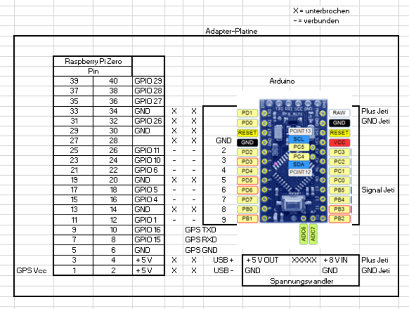
| Raspberry Pi | übertragenes Bit | Arduino / GPS |
| GPIO02 | 1er | Ard.: Bit1Pin = 9 |
| GPIO03 | 2er | Ard.: Bit2Pin = 8 |
| GPIO04 | 4er | Ard.: Bit4Pin = 7 |
| GPIO17 | 8er | Ard.: Bit8Pin = 5 |
| GPIO27 | 16er | Ard.: Bit16Pin = 4 |
| GPIO22 | 32er | Ard.: Bit32Pin = 3 |
| Pin 1 | +3,3 V | GPS: Vcc |
| Pin 6 | Masse | GPS: Masse |
| Pin 8 | TX / RX | GPS TX / RX |
| Pin 10 | TX / RX | GPS: TX / RX |
 /*
  Jeti Sensor EX Telemetry C++ Library
  Simple Main program
  --------------------------------------------------------------------
  Copyright (C) 2015 Bernd Wokoeck
  *** Extended notice on additional work and copyrights, see header of JetiExProtocol.cpp ***
  Wiring:
    Arduino Mini  TXD-Pin 0 <-- Receiver "Ext." input (orange cable)
  Ressources:
    Uses built in UART of Arduini Mini Pro 328 or one of 3 Teensy UARTs
  Version history:
  0.90   11/22/2015  created
  0.95   12/23/2015  new sample sensors for GPS and date/time
  0.96   02/21/2016  comPort number as optional parameter for Teensy in Start(...)
                     sensor device id as optional parameter (SetDeviceId(...))
  1.02   03/28/2017  New sensor memory management. Sensor data can be located in PROGMEM
**************************************************************/
#include "JetiExProtocol.h"
#include
LiquidCrystal_I2C  lcd (0x27, 2, 1, 0, 4, 5, 6, 7); // PCF8754 - 0x27, PCF8754A - 0x3F !
JetiExProtocol jetiEx;
enum
{
    ID_FREQUENCE_COUNT = 1,
    ID_FREQUENCE_AVERAGE_LOW = 2,
    ID_FREQUENCE_AVERAGE_HIGH = 3,
};
// id from 1..15
JETISENSOR_CONST sensors[] PROGMEM =
{
    // id            name          unit           data type     precision 0->0, 1->0.0, 2->0.00
    { ID_FREQUENCE_COUNT,          "FreqCnt",     "Ch",         JetiSensor::TYPE_14b, 0 },
    { ID_FREQUENCE_AVERAGE_LOW,    "FreqAvgLow",  "Ch",         JetiSensor::TYPE_14b, 0 },
    { ID_FREQUENCE_AVERAGE_HIGH,   "FreqAvgHigh", "Ch",         JetiSensor::TYPE_14b, 0 },
    0 // end of array
};
long counter = 0;
const int CntBit1Pin = 6; //Digital
const int CntBit2Pin = 7; //Digital
const int CntBit4Pin = 8; //Digital
const int CntBit8Pin = 9; //Digital
const int AverageLowPin = 10; //Digital
const int AverageHighPin =11; //Digital
int CntBit1Val = 0;
int CntBit2Val = 0;
int CntBit4Val = 0;
int CntBit8Val = 0;
int AverageLowVal = 0;
int AverageHighVal =0;
void setup()
{
#ifdef CORE_TEENSY
    Serial.begin ( 9600 );
#endif
// Pinmodes for switches
    pinMode (CntBit1Pin, INPUT);
    pinMode (CntBit2Pin, INPUT);
    pinMode (CntBit4Pin, INPUT);
    pinMode (CntBit8Pin, INPUT);
    pinMode (AverageLowPin, INPUT);
    pinMode (AverageHighPin, INPUT);
    jetiEx.Start ( "MSF", sensors );
// jetiEx.SetJetiboxText( JetiExProtocol::LINE1, "Start 1" );
// jetiEx.SetJetiboxText( JetiExProtocol::LINE2, "Start 2" );
// start LCD-Display
    lcd.begin (16, 2);            // for 16 x 2 LCD module
    lcd.setBacklightPin (3, POSITIVE);
    lcd.setBacklight (HIGH);
    lcd.home ();
    lcd.print ("2,4 GHz Messung");
    lcd.setCursor (0, 1);
    lcd.print ("Rainer & Jochen");
    delay (3000);
    lcd.clear ();
}
void loop()
{
    long value;
    // Read switches
    CntBit1Val = digitalRead (CntBit1Pin);
    CntBit2Val = digitalRead (CntBit2Pin);
    CntBit4Val = digitalRead (CntBit4Pin);
    CntBit8Val = digitalRead (CntBit8Pin);
    AverageLowVal = digitalRead (AverageLowPin);
    AverageHighVal = digitalRead (AverageHighPin);
    value = CntBit1Val*1+CntBit2Val*2+CntBit4Val*4+CntBit8Val*8;
    value = value*6 ;
// counter++; // zählt counter 1 hoch identisch wie counter = counter+1;
// value = counter%100 ;
    if (AverageLowVal != 0) {
        jetiEx.SetSensorValue ( ID_FREQUENCE_AVERAGE_LOW,  value );
        lcd.setCursor (0, 1);
        lcd.print ("Low: ");
        lcd.print (value);
    } else if (AverageHighVal != 0) {
        jetiEx.SetSensorValue ( ID_FREQUENCE_AVERAGE_HIGH,  value );
        lcd.setCursor (8, 1);
        lcd.print ("High: ");
        lcd.print (value);
    } else {
        jetiEx.SetSensorValue ( ID_FREQUENCE_COUNT, value );
        lcd.home ();
        lcd.setCursor (1, 0);
        lcd.print ("Actual: ");
        lcd.print (value);
        lcd.print (" Ch");
    }
//  /* add your main program code here */
//
//jetiEx.SetSensorValue( ID_FREQUENCE_COUNT,  (counter) );
//jetiEx.SetSensorValue( ID_FREQUENCE_AVERAGE_LOW,  (counter%100) );
//jetiEx.SetSensorValue( ID_FREQUENCE_AVERAGE_HIGH,  (counter%20) );
    jetiEx.DoJetiSend();
}
 /*
Jeti Sensor EX Telemetry C++ Library

  Simple Main program
  --------------------------------------------------------------------

  Copyright (C) 2015 Bernd Wokoeck

  *** Extended notice on additional work and copyrights, see header of JetiExProtocol.cpp ***

  Wiring:

    Arduino Mini  TXD-Pin 0 <-- Receiver "Ext." input (orange cable)

  Ressources:
    Uses built in UART of Arduini Mini Pro 328 or one of 3 Teensy UARTs

  Version history:
  0.90   11/22/2015  created
  0.95   12/23/2015  new sample sensors for GPS and date/time
  0.96   02/21/2016  comPort number as optional parameter for Teensy in Start(...)
                     sensor device id as optional parameter (SetDeviceId(...))
  1.02   03/28/2017  New sensor memory management. Sensor data can be located in PROGMEM

**************************************************************/

#include "JetiExProtocol.h"
#include
LiquidCrystal_I2C  lcd(0x27, 2, 1, 0, 4, 5, 6, 7); // PCF8754 - 0x27, PCF8754A - 0x3F !
JetiExProtocol jetiEx;

enum
{
  ID_FREQUENCE_COUNT = 1,
  ID_FREQUENCE_AVERAGE_LOW = 2,
  ID_FREQUENCE_AVERAGE_HIGH = 3,

};

// id from 1..15
JETISENSOR_CONST sensors[] PROGMEM =
{
  // id            name          unit           data type     precision 0->0, 1->0.0, 2->0.00
  { ID_FREQUENCE_COUNT,          "FreqCnt",     "Ch",         JetiSensor::TYPE_14b, 0 },
  { ID_FREQUENCE_AVERAGE_LOW,    "FreqAvgLow",  "Ch",         JetiSensor::TYPE_14b, 0 },
  { ID_FREQUENCE_AVERAGE_HIGH,   "FreqAvgHigh", "Ch",         JetiSensor::TYPE_14b, 0 },

  0 // end of array
};

long counter = 0;
const int CntBit1Pin = 9; //Digital
const int CntBit2Pin = 7; //Digital
const int CntBit4Pin = 6; //Digital
const int CntBit8Pin = 4; //Digital
const int CntBit16Pin = 3; //Digital
const int CntBit32Pin = 2; //Digital

int CntBit1Val = 0;
int CntBit2Val = 0;
int CntBit4Val = 0;
int CntBit8Val = 0;
int CntBit16Val = 0;
int CntBit32Val = 0;
void setup()
{
#ifdef CORE_TEENSY
  Serial.begin( 9600 );
#endif

  // Pinmodes for switches ans pullup

  pinMode(CntBit1Pin, INPUT); // set pin to input
  digitalWrite(CntBit1Pin, HIGH); // turn on pullup resistors
  pinMode(CntBit2Pin, INPUT);
  digitalWrite(CntBit2Pin, HIGH);
  pinMode(CntBit4Pin, INPUT);
  digitalWrite(CntBit4Pin, HIGH);
  pinMode(CntBit8Pin, INPUT);
  digitalWrite(CntBit8Pin, HIGH);
  pinMode(CntBit16Pin, INPUT);
  digitalWrite(CntBit16Pin, HIGH);
  pinMode(CntBit32Pin, INPUT);
  digitalWrite(CntBit32Pin, HIGH);
  jetiEx.Start( "MSF", sensors );

  // jetiEx.SetJetiboxText( JetiExProtocol::LINE1, "Start 1" );
  // jetiEx.SetJetiboxText( JetiExProtocol::LINE2, "Start 2" );

//  // start LCD-Display
//  lcd.begin (16, 2);            // for 16 x 2 LCD module
//  lcd.setBacklightPin(3, POSITIVE);
//  lcd.setBacklight(HIGH);
//  lcd.home ();
//  lcd.print("2,4 GHz Messung");
//  lcd.setCursor (0, 1);
//  lcd.print("Rainer & Jochen");
//  delay(3000);
//  lcd.clear ();

}

void loop()
{
  long value;
  // Read switches
  CntBit1Val = digitalRead(CntBit1Pin);
  CntBit2Val = digitalRead(CntBit2Pin);
  CntBit4Val = digitalRead(CntBit4Pin);
  CntBit8Val = digitalRead(CntBit8Pin);
  CntBit16Val = digitalRead(CntBit16Pin);
  CntBit32Val = digitalRead(CntBit32Pin);

  value = CntBit1Val * 1 + CntBit2Val * 2 + CntBit4Val * 4 + CntBit8Val * 8 + CntBit16Val * 16 + CntBit32Val * 32;
  //  value = value*6 ;
  value = value * 1 ;

  jetiEx.SetSensorValue( ID_FREQUENCE_AVERAGE_LOW,  value );
  lcd.setCursor (0, 1);
  lcd.print ("Avg:"); lcd.print(value); // Durchschnittswert vom Raspberry übermittelt
  lcd.setCursor (7, 1);
  lcd.print ("3:"); lcd.print("xx"); // Durchschnittswert der letzten 3 Sekunden
  lcd.setCursor (12, 1);
  lcd.print ("8:"); lcd.print("yy"); // Durchschnittswert der letzten 8 Sekunden
  char AnzeigeBalken[20];
  int xCount = value / 5;
  sprintf(AnzeigeBalken, "");
  for (int i = 0; i < xCount; i++) {
    sprintf(AnzeigeBalken, "%s%s", AnzeigeBalken, "=");
  }
//  lcd.setCursor (1, 0);
//  lcd.print (AnzeigeBalken);
//  delay(500);
//  lcd.clear ();

  //  counter++; // zählt counter 1 hoch identisch wie counter = counter+1;
  //  /* add your main program code here */
  //
  //  jetiEx.SetSensorValue( ID_FREQUENCE_COUNT,  (counter) );
  //  jetiEx.SetSensorValue( ID_FREQUENCE_AVERAGE_LOW,  (counter%100) );
  //  jetiEx.SetSensorValue( ID_FREQUENCE_AVERAGE_HIGH,  (counter%20) );

  jetiEx.DoJetiSend();
}
 /*
Jeti Sensor EX Telemetry C++ Library

  Simple Main program
  --------------------------------------------------------------------

  Copyright (C) 2015 Bernd Wokoeck

  *** Extended notice on additional work and copyrights, see header of JetiExProtocol.cpp ***

  Wiring:

    Arduino Mini  TXD-Pin 0 <-- Receiver "Ext." input (orange cable)

  Ressources:
    Uses built in UART of Arduini Mini Pro 328 or one of 3 Teensy UARTs

  Version history:
  0.90   11/22/2015  created
  0.95   12/23/2015  new sample sensors for GPS and date/time
  0.96   02/21/2016  comPort number as optional parameter for Teensy in Start(...)
                     sensor device id as optional parameter (SetDeviceId(...))
  1.02   03/28/2017  New sensor memory management. Sensor data can be located in PROGMEM

**************************************************************/

#include "JetiExProtocol.h"
#include
LiquidCrystal_I2C  lcd(0x27, 2, 1, 0, 4, 5, 6, 7); // PCF8754 - 0x27, PCF8754A - 0x3F !
JetiExProtocol jetiEx;

enum
{
  ID_FREQUENCE_COUNT = 1,
  ID_FREQUENCE_AVERAGE_LOW = 2,
  ID_FREQUENCE_AVERAGE_HIGH = 3,

};

// id from 1..15
JETISENSOR_CONST sensors[] PROGMEM =
{
  // id            name          unit           data type     precision 0->0, 1->0.0, 2->0.00
  { ID_FREQUENCE_COUNT,          "FreqCnt",     "Ch",         JetiSensor::TYPE_14b, 0 },
  { ID_FREQUENCE_AVERAGE_LOW,    "FreqAvgLow",  "Ch",         JetiSensor::TYPE_14b, 0 },
  { ID_FREQUENCE_AVERAGE_HIGH,   "FreqAvgHigh", "Ch",         JetiSensor::TYPE_14b, 0 },

  0 // end of array
};

long counter = 0;
const int CntBit1Pin = 9; //Digital
const int CntBit2Pin = 8; //Digital
const int CntBit4Pin = 7; //Digital
const int CntBit8Pin = 5; //Digital
const int CntBit16Pin = 4; //Digital
const int CntBit32Pin = 3; //Digital

int CntBit1Val = 0;
int CntBit2Val = 0;
int CntBit4Val = 0;
int CntBit8Val = 0;
int CntBit16Val = 0;
int CntBit32Val = 0;
void setup()
{
#ifdef CORE_TEENSY
  Serial.begin( 9600 );
#endif

  // Pinmodes for switches ans pullup

  pinMode(CntBit1Pin, INPUT); // set pin to input
  digitalWrite(CntBit1Pin, HIGH); // turn on pullup resistors
  pinMode(CntBit2Pin, INPUT);
  digitalWrite(CntBit2Pin, HIGH);
  pinMode(CntBit4Pin, INPUT);
  digitalWrite(CntBit4Pin, HIGH);
  pinMode(CntBit8Pin, INPUT);
  digitalWrite(CntBit8Pin, HIGH);
  pinMode(CntBit16Pin, INPUT);
  digitalWrite(CntBit16Pin, HIGH);
  pinMode(CntBit32Pin, INPUT);
  digitalWrite(CntBit32Pin, HIGH);
  jetiEx.Start( "MSF", sensors );

  // jetiEx.SetJetiboxText( JetiExProtocol::LINE1, "Start 1" );
  // jetiEx.SetJetiboxText( JetiExProtocol::LINE2, "Start 2" );

//  // start LCD-Display
//  lcd.begin (16, 2);            // for 16 x 2 LCD module
//  lcd.setBacklightPin(3, POSITIVE);
//  lcd.setBacklight(HIGH);
//  lcd.home ();
//  lcd.print("2,4 GHz Messung");
//  lcd.setCursor (0, 1);
//  lcd.print("Rainer & Jochen");
//  delay(3000);
//  lcd.clear ();

}

void loop()
{
  long value;
  // Read switches
  CntBit1Val = digitalRead(CntBit1Pin);
  CntBit2Val = digitalRead(CntBit2Pin);
  CntBit4Val = digitalRead(CntBit4Pin);
  CntBit8Val = digitalRead(CntBit8Pin);
  CntBit16Val = digitalRead(CntBit16Pin);
  CntBit32Val = digitalRead(CntBit32Pin);

  value = CntBit1Val * 1 + CntBit2Val * 2 + CntBit4Val * 4 + CntBit8Val * 8 + CntBit16Val * 16 + CntBit32Val * 32;
  //  value = value*6 ;
  value = value * 1 ;

  jetiEx.SetSensorValue( ID_FREQUENCE_AVERAGE_LOW,  value );
  lcd.setCursor (0, 1);
  lcd.print ("Avg:"); lcd.print(value); // Durchschnittswert vom Raspberry übermittelt
  lcd.setCursor (7, 1);
  lcd.print ("3:"); lcd.print("xx"); // Durchschnittswert der letzten 3 Sekunden
  lcd.setCursor (12, 1);
  lcd.print ("8:"); lcd.print("yy"); // Durchschnittswert der letzten 8 Sekunden
  char AnzeigeBalken[20];
  int xCount = value / 5;
  sprintf(AnzeigeBalken, "");
  for (int i = 0; i < xCount; i++) {
    sprintf(AnzeigeBalken, "%s%s", AnzeigeBalken, "=");
  }
//  lcd.setCursor (1, 0);
//  lcd.print (AnzeigeBalken);
//  delay(500);
//  lcd.clear ();

  //  counter++; // zählt counter 1 hoch identisch wie counter = counter+1;
  //  /* add your main program code here */
  //
  //  jetiEx.SetSensorValue( ID_FREQUENCE_COUNT,  (counter) );
  //  jetiEx.SetSensorValue( ID_FREQUENCE_AVERAGE_LOW,  (counter%100) );
  //  jetiEx.SetSensorValue( ID_FREQUENCE_AVERAGE_HIGH,  (counter%20) );

  jetiEx.DoJetiSend();
}